International Journal of Electrical and Computer Systems (IJECS)
ISSN: 1929-2716

Volume 3, Year 2017 - Pages 1-8
DOI: 10.11159/ijecs.2017.001
Transmission Code Design for Asynchronous Full-Duplex Relaying
Ran Cai1,2, Yun Liu3, P. C. Ching4
1 Postdoctoral Scientific Research Workstation,
Postal Savings Bank of China
P. R. China
Cairan@psbc.com
2 PBC School of Finance, Tsinghua University
P. R. China
3 Huawei Technologies
P. R. China
Liuyun2501@gmail.com
4Department of Electronic Engineering, the Chinese University of Hong Kong
Hong Kong SAR of China
Pcching@ee.cuhk.edu.hk
Abstract - Full-duplex relay systems have emerged as a promising solution to improve spectrum efficiency. Due to residual self-interference, space-time code may lose diversity gain. This study addresses this problem caused by self-interference and asynchronous transmission in full-duplex relay systems. In particular, a space-time code is designed at the transmitter and the relay to achieve diversity gain at the presence of residual self-interference. During transmission, the code at the relay can be used to estimate the residual self-interference caused by imperfect channel knowledge. The estimation result can be used to further reduce self-interference. Diversity gain can be achieved at the destination as a result of the reduction of the residual self-interference. Both theoretical analysis and simulation results demonstrate the diversity gain of our design in asynchronous full-duplex relay systems.
Keywords: Full-duplex relay, asynchronous transmission, self-interference, space-time code.
© Copyright 2017 Authors - This is an Open Access article published under the Creative Commons Attribution License terms. Unrestricted use, distribution, and reproduction in any medium are permitted, provided the original work is properly cited.
Date Received: 2016-06-27
Date Accepted: 2016-09-23
Date Published: 2017-08-09
1. Introduction
The full-duplex transmission mode has been investigated to provide high data rate and diversity gain in relay systems [1-6]. Full-duplex relay systems can theoretically double the spectrum efficiency of traditional half-duplex relay systems. Moreover, a full-duplex node can sense other transmissions during its transmitting, to avoid the hidden node problem [7].
A major hindrance encountered in full-duplex relay systems is self-interference because signal transmission and reception are simultaneously performed at the same relay in a full-duplex mode. Worse still, self-interference may be much stronger than the signal of interest. Many efforts have been exerted at cancelling the self- interference [8-12], and current self-interference cancellation can be achieved in the range between 66 and 74 dB [13]. However, as discussed in [13], given the large residual self-interference (RSI), the 66 dB cancellation is insufficient for full-duplex relay systems to outperform half-duplex relay systems in terms of data rate. Furthermore, the signal cancellation techniques require a bulky radio-frequency attenuator, which is expensive to implement [7]. Moreover, the high RSI in full-duplex relay systems causes a high bit error, which presents diversity-zero performance; that is, error floor exists in a high signal-to-noise ratio (SNR) region [14]. To alleviate this problem, [15, 16] designed optimal power allocation.
Asynchronous transmission is another hindrance encountered in full-duplex relay systems in practice. Two transmission links exist in a typical full-duplex relay system: a direct link from the source to the destination and a relay link that connects the source and the destination. The direct link contains the path delay from the source to the destination, and the relay link contains both the processing delay at the relay and transmission delay. The delay difference between the relay and the direct links results in asynchronous transmission. Such asynchronous transmission may cause two problems: a loss in diversity and an increase in decoding complexity. For an ideal full-duplex relay systems, the space-time code (STC) can be adopted at the source and relays to harvest diversity gain [17, 18]. However, the code structure of STC may not be full rank because of asynchronous transmission, thereby resulting in diversity loss [17, 18]. For maximum-likelihood (ML) decoding, the decoding complexity may increase exponentially with code length and linearly with delay difference.
The work in [19] considered a full-duplex system with no path delay. The proposed code design in [19] added an intentional delay on each relay to form a full diversity code structure, thereby ensuring full diversity. However, such code structure may confront diversity loss when considering path delay and processing delay at relays. In [18], the code design deploys a distributed linear convolutive code to ensure full diversity. However, the code design requires perfect knowledge of the self-interference channel for encoding, and its decoding is complexity prohibitive when the code length is long.
In the present work, we jointly consider the effects of RSI and delays. The code structure in our code design is specifically separated into two parts. The first part is used to estimate the RSI at the relay. With the estimation result, the relay can cancel the RSI when transmitting the second part. Our design improves the bit error rate (BER) performance in asynchronous full-duplex relay systems.
2. Asynchronous Full-Duplex Relay System
We consider an asynchronous full-duplex relay system as shown in Figure 1,
in which the relay R helps the transmission between source S and destination D.
A direct transmission link exists between source S and destination D. The
direct and relay links form a 2 × 1 system with potential of diversity 2. The
channel fading and delay coefficient of the direct link are ![]() and
and ![]() , respectively; those between the
source and the relay are
, respectively; those between the
source and the relay are ![]() and
and ![]() , respectively; and those between the
relay and the destination are
, respectively; and those between the
relay and the destination are ![]() and
and ![]() , respectively. The channel fading
coefficients
, respectively. The channel fading
coefficients ![]() ,
, ![]() and
and ![]() follow complex Gaussian distribution
follow complex Gaussian distribution ![]() , and remain unchanged during the
transmission of one code block. The transmission power of the source is
, and remain unchanged during the
transmission of one code block. The transmission power of the source is ![]() . The delay coefficients are known at
each node as in [17, 18]. The delay difference is given as
. The delay coefficients are known at
each node as in [17, 18]. The delay difference is given as

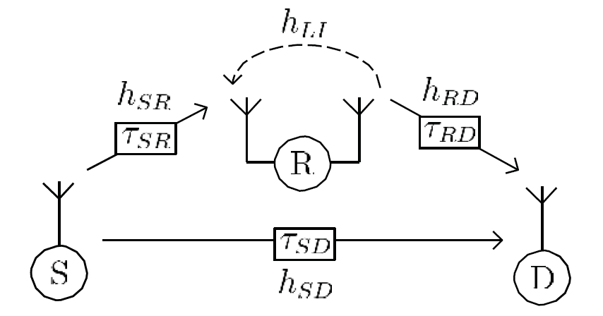
2.1. Residual Self-Interference
The relay works in full-duplex mode,
which means that the relay simultaneously receives and transmits signals within
the same frequency. The loop channel between the transmit and receive antennas
of the relay is denoted as ![]() , which remains unchanged during the
transmission of one code block [13]. At the relay, the estimation of
, which remains unchanged during the
transmission of one code block [13]. At the relay, the estimation of ![]() is
is ![]() . Theoretically, if
. Theoretically, if ![]() , then we can perfectly cancel the
self-interference signal. However, the estimation of
, then we can perfectly cancel the
self-interference signal. However, the estimation of ![]() is not perfect in practice. The
estimation error is defined as
is not perfect in practice. The
estimation error is defined as ![]() , where
, where ![]() is
modeled as a complex random variable that varies from each code block to another,
but remains unchanged in the same code block. Many efforts have been exerted at
improving the self-interference cancellation [8-13]. For a typical radio
transmission, the SNR is approximately 30 dB. The self-interference can be
millions of times stronger (60 dB or more) than a received signal. In such
case, nearly 100 dB cancellation of self-interference is required to ensure the
30 dB gap in the signal and interference plus noise. Currently, many schemes
[8-13] that use analog cancellation, digital cancellation, antenna separation,
or some combination of the above are able to cancel the self-interference
around 74 dB [9, 13], such that the power of RSI can be as low as −10dB
compared with the signal of interest.
is
modeled as a complex random variable that varies from each code block to another,
but remains unchanged in the same code block. Many efforts have been exerted at
improving the self-interference cancellation [8-13]. For a typical radio
transmission, the SNR is approximately 30 dB. The self-interference can be
millions of times stronger (60 dB or more) than a received signal. In such
case, nearly 100 dB cancellation of self-interference is required to ensure the
30 dB gap in the signal and interference plus noise. Currently, many schemes
[8-13] that use analog cancellation, digital cancellation, antenna separation,
or some combination of the above are able to cancel the self-interference
around 74 dB [9, 13], such that the power of RSI can be as low as −10dB
compared with the signal of interest.
2.2. Transmission Model
At the beginning, the source S transmits a sequence s[1 : ![]() ],
where
],
where ![]() ∈ Z+
is the length of the sequence. In the amplifying-and-forward mode, the received
signal
∈ Z+
is the length of the sequence. In the amplifying-and-forward mode, the received
signal ![]() and the transmitted signal
and the transmitted signal ![]() at the relay R at time
at the relay R at time ![]() are expressed as follows:
are expressed as follows:
where ![]() is the transmission power at the
source S,
is the transmission power at the
source S, ![]() is
the amplifying factor at the relay R, and
is
the amplifying factor at the relay R, and ![]() that follows
that follows ![]() is the noise at the relay R,
is the noise at the relay R, ![]() = 1, 2,...,
= 1, 2,..., ![]() . We consider that the relay can use
. We consider that the relay can use ![]() to cancel the self-interference [8-13].
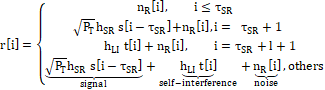
After self-interference cancellation, the received signal becomes
to cancel the self-interference [8-13].
After self-interference cancellation, the received signal becomes

where ![]() is a RSI term and
is a RSI term and ![]() is a random variable. Then, the transmitted signal
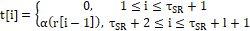
is a random variable. Then, the transmitted signal ![]() based on
based on ![]() (
(![]() ) is given as
) is given as

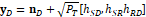
The received signal vector after self-interference cancellation is

The
coefficients ![]() are caused by RSI terms, where
are caused by RSI terms, where ![]() is typically -10 dB, as discussed in
Section 2.1. Without loss of generality, we set the fixed-gain coefficient
is typically -10 dB, as discussed in
Section 2.1. Without loss of generality, we set the fixed-gain coefficient ![]() , and model
, and model ![]()
![]() with
with ![]() .
.
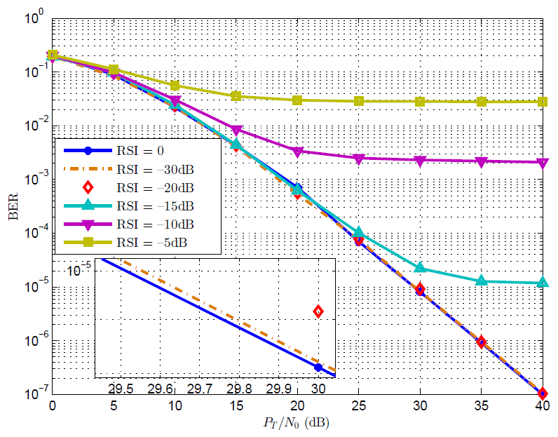
2.3. Performance Loss from Residual Self-Interference
Since the self-interference channel ![]() is much stronger than other channel
coefficients, the estimation accuracy of
is much stronger than other channel
coefficients, the estimation accuracy of ![]() is very important to full-duplex
relay networks. The existence of channel estimation error would cause severe
bit error rate (BER) degradation in delay diversity code [22] as shown by our
simulation in Figure 2. If the power of RSI is −10dB
or −15dB, the BER simulation would encounter error floor around
is very important to full-duplex
relay networks. The existence of channel estimation error would cause severe
bit error rate (BER) degradation in delay diversity code [22] as shown by our
simulation in Figure 2. If the power of RSI is −10dB
or −15dB, the BER simulation would encounter error floor around ![]() or
or ![]() , respectively. From the state of the
art, the power of RSI is around −10dB [9, 13]. For cases with RSI as
−20dB and −30dB, the performance degradation is not so severe when
, respectively. From the state of the
art, the power of RSI is around −10dB [9, 13]. For cases with RSI as
−20dB and −30dB, the performance degradation is not so severe when ![]() /
/![]() is lower than 40dB. In other words,
for practical applications, if we manage to reduce the RSI to −20dB or
below, the effect of RSI may not be so significant.
is lower than 40dB. In other words,
for practical applications, if we manage to reduce the RSI to −20dB or
below, the effect of RSI may not be so significant.
3. Estimation of Residual Self-Interference
In the above description, we focus on the transmitted and received signals at relay R. Specifically, source S transmits ![]() symbols
and remains silent in the next one symbol duration in each transmission block,
where channel coefficients remain unchanged. Accurate estimation of
symbols
and remains silent in the next one symbol duration in each transmission block,
where channel coefficients remain unchanged. Accurate estimation of ![]() is very important to cancel the
self-interference at the relay. However, the estimation error
is very important to cancel the
self-interference at the relay. However, the estimation error ![]() exists in practice. To cancel the RSI, it is important to accurately estimate
exists in practice. To cancel the RSI, it is important to accurately estimate ![]() on
the relay. However, the received signal vector in (4) contains s[1 :
on
the relay. However, the received signal vector in (4) contains s[1 : ![]() ], which is unknown to the relay.
], which is unknown to the relay.
In this section, we propose a method of joint estimation and detection. After retransmitting the ![]() symbols,
the received signal vector at relay R is given in (4). Term
symbols,
the received signal vector at relay R is given in (4). Term ![]() appears
repeatedly
appears
repeatedly ![]() times
in
times
in ![]() . Thus, all these signals can be used
to estimate
. Thus, all these signals can be used
to estimate ![]() . In this section, we show how to
estimate the RSI at relay R. We first transform (4) into the following linear
model:
. In this section, we show how to
estimate the RSI at relay R. We first transform (4) into the following linear
model:
In this
equation, the relay knows the received ![]() -length signal sequence
-length signal sequence ![]() , transmission power
, transmission power ![]() and channel coefficient
and channel coefficient ![]() , and the relay aims to derive the
channel estimation error
, and the relay aims to derive the
channel estimation error ![]() and
signal
and
signal ![]() -1)-length sequence
-1)-length sequence ![]() . In this section, we propose
estimation methods at the relay. The estimation results are denoted as
. In this section, we propose
estimation methods at the relay. The estimation results are denoted as ![]() . Ideally, perfect channel estimation
leads to
. Ideally, perfect channel estimation
leads to ![]() , and perfect signal detection lead to
, and perfect signal detection lead to
![]() .
.
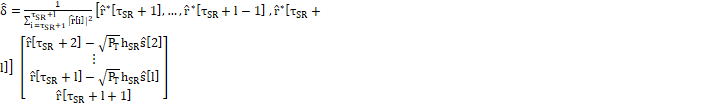
From (5), we can derive the estimation of ![]() in (6).
in (6).
The processes of RSI estimation and signal detection essentially involve finding the ![]() that maximizes the logarithm probability
in (7).
that maximizes the logarithm probability
in (7).

The basic idea
is to use all possible combinations of ![]() to estimate
to estimate ![]() in
(6), and then calculate
in
(6), and then calculate ![]() to find the maximum one. One simple
approach is to calculate (7) using all possible candidates of
to find the maximum one. One simple
approach is to calculate (7) using all possible candidates of ![]() to obtain the values of
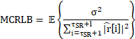
to obtain the values of ![]() from the maximum one. When
from the maximum one. When ![]() , the modified Cram
, the modified Cram ![]() r-Rao lower bound (MCRLB) [21] for estimating
r-Rao lower bound (MCRLB) [21] for estimating ![]() is in (8) is
is in (8) is
When SNR is
significantly high, the detection is likely to be error-free, and the estimated
b ![]() may not be affected by detection
errors. At the relay, the complexity of this estimation scheme is
may not be affected by detection
errors. At the relay, the complexity of this estimation scheme is ![]() .
.
4. Design of Space-Time Code
In this section, we propose for the
asynchronous full-duplex relay system an STC that estimates ![]() first to cancel the RSI during the relay transmission at the relay. We also analyze the diversity gain, code rate, and decoding complexity of our design.
first to cancel the RSI during the relay transmission at the relay. We also analyze the diversity gain, code rate, and decoding complexity of our design.
We assume that source S intends to
transmit an ![]() -symbol
sequence
-symbol
sequence ![]() to
the destination in a full-duplex relay system, as shown in Figure 1. The
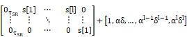
transmitted signal vector by source S is defined as:
to
the destination in a full-duplex relay system, as shown in Figure 1. The
transmitted signal vector by source S is defined as:
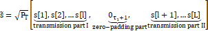
where
the first part of the transmission is used to estimate the RSI at the relay.
With the estimation result, relay R can cancel the RSI when sending the second
part. The zero-padding part is inserted after transmitting ![]() (
(![]()
![]() ) symbols to separate the two
transmission parts, in which
) symbols to separate the two
transmission parts, in which ![]() is the delay deference defined in
(1).
is the delay deference defined in
(1).
The relay
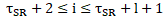
receives and transmits signals in the following procedure. During the first ![]() time slots, the relay jointly
estimates
time slots, the relay jointly
estimates ![]() and detects
and detects ![]() to obtain
to obtain ![]() by
applying scheme in Section 3. Meanwhile, during time slots [
by
applying scheme in Section 3. Meanwhile, during time slots [![]()
![]() ], the relay directly transmits the
received signal in the previous time slot. After reducing the RSI by
], the relay directly transmits the
received signal in the previous time slot. After reducing the RSI by ![]() ,
the relay transmits the processed signals in the time slots [
,
the relay transmits the processed signals in the time slots [![]()
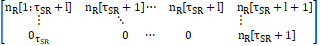
![]() ]. The received signal vector at the
relay is
]. The received signal vector at the
relay is

where
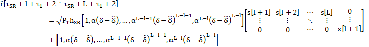
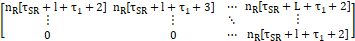
can be derived from equation (2). The transmitted signal vector at the relay is

where
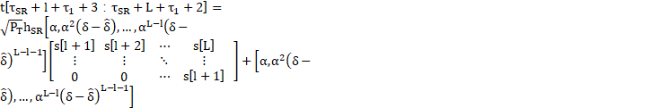
can be derived from equation (3). The transmission schemes in the transmitter and relay form an STC structure. At destination D, the received signal vector is
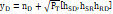

where ![]() is the noise vector at destination D,
the channel coefficients are known. To illustrate the code structure, we give
the following example.
is the noise vector at destination D,
the channel coefficients are known. To illustrate the code structure, we give
the following example.
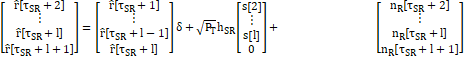
Example: We let [![]() ,
,![]() ,
,![]() ]
= [0, 0, 0],
]
= [0, 0, 0], ![]() ,
, ![]() = 2, and
= 2, and ![]() = 5. For simplicity, we let
= 5. For simplicity, we let ![]() and
and ![]() .
.
Equation (10) becomes

Equation (11) shows that the first ![]() symbols,
that is,
symbols,
that is, ![]() [1]
and
[1]
and ![]() [2],
do not interfere with the remaining
[2],
do not interfere with the remaining ![]() symbols, that is,
symbols, that is, ![]() [3],
[3], ![]() [4]
and
[4]
and ![]() [5],
because of the zero-padding
[5],
because of the zero-padding ![]() in (9). The decoding methods at the
destination are different for the first
in (9). The decoding methods at the
destination are different for the first ![]() symbols and the remaining
symbols and the remaining ![]() symbols. An RSI exists for the first
symbols. An RSI exists for the first ![]() symbols.
We assume that the destination can obtain the resulting
symbols.
We assume that the destination can obtain the resulting ![]() from
the relay so that the destination can conduct exhaustive search on the
from
the relay so that the destination can conduct exhaustive search on the ![]() symbols.
In practice, even if the destination cannot perfectly obtain
symbols.
In practice, even if the destination cannot perfectly obtain ![]() from
the relay, it can still detect the signal and similarly estimate the RSI as the
relay does in Section 3, thereby resulting in the same exhaustive search on the
from
the relay, it can still detect the signal and similarly estimate the RSI as the
relay does in Section 3, thereby resulting in the same exhaustive search on the ![]() symbols.
A remaining RSI exists for the other L−
symbols.
A remaining RSI exists for the other L− ![]() symbols because
symbols because ![]() . However, given that this remaining
RSI after cancellation is sufficiently small, we can treat it as noise in the
decoding process for the rest L −
. However, given that this remaining
RSI after cancellation is sufficiently small, we can treat it as noise in the
decoding process for the rest L − ![]() symbols.
symbols.
Remark 1. (Diversity Gain) In an asynchronous full-duplex relay system with one relay, one single-antenna source, and one single-antenna destination, the proposed STC achieves full diversity, that is, diversity order 2, with the perfect estimation of the RSI. This occurs because the reduction of self-interference makes the direct and relay links form an ideal 2 × 1 system.
Remark 2. (Code Rate Analysis) The code rate of the proposed STC is ![]() . When L is sufficiently large, this
rate approaches 1 symbol/channel.
. When L is sufficiently large, this
rate approaches 1 symbol/channel.
Remark 3. (Decoding Complexity) The decoding complexity of the proposed STC at the destination is O(![]() + (L − l)
+ (L − l) ![]() ). For the first
). For the first ![]() symbols, the destination obtains the parameter
symbols, the destination obtains the parameter ![]() from the relay and exhaustively search over all possible s[1:l] with complexity
from the relay and exhaustively search over all possible s[1:l] with complexity ![]() . For the remaining L − l
symbols, the relay reduces the RSI, and the remaining RSI is treated as noise
at the destination. The Viterbi decoder, an equivalent form of ML decoder, is
applied to decode s[l+1 : L] with complexity
. For the remaining L − l
symbols, the relay reduces the RSI, and the remaining RSI is treated as noise
at the destination. The Viterbi decoder, an equivalent form of ML decoder, is
applied to decode s[l+1 : L] with complexity ![]() .
.
In practice, the decoding complexity is low when l is small and a simple constellation, such as QPSK is adopted. However, the estimation error variance is large when l is small, according to (8). If high-order constellations, such as 16QAM and
64QAMare adopted, then a large ![]() leads to high complexity.
leads to high complexity.
5. Simulations
In this section, we simulate the mean
square error (MSE) of RSI estimation and BER performance of the proposed STC
with respect to SNR ![]() /
/![]() , where
, where ![]() is the noise power spectrum density.
The amplifying factor
is the noise power spectrum density.
The amplifying factor ![]() , and RSI
, and RSI ![]() dB, as described in Section 2.1. The
adopted constellation adopted is QPSK.
dB, as described in Section 2.1. The
adopted constellation adopted is QPSK.
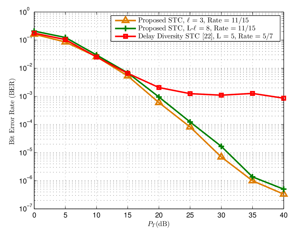
Figure 3 compares the performance of the proposed STC and delay diversity STC [22] when ![]() . For the sake of fairness, all the
schemes use an ML decoder at the destination. The BER performance of delay
diversity STC exhibits the error floor problem around BER
. For the sake of fairness, all the
schemes use an ML decoder at the destination. The BER performance of delay
diversity STC exhibits the error floor problem around BER ![]() . This problem is attributed to the
existence of the RSI. By contrast, our proposed STC avoids such problems in the
considered high
. This problem is attributed to the
existence of the RSI. By contrast, our proposed STC avoids such problems in the
considered high ![]() /
/![]() region. For the proposed STC, the BER
performance of the
region. For the proposed STC, the BER
performance of the ![]() and
L −
and
L − ![]() parts,
which use different decoding methods as discussed in Section 4, are plotted
separately. Both parts of the proposed STC demonstrate diversity gain and
therefore outperform delay diversity STC in terms of BER performance.
parts,
which use different decoding methods as discussed in Section 4, are plotted
separately. Both parts of the proposed STC demonstrate diversity gain and
therefore outperform delay diversity STC in terms of BER performance.
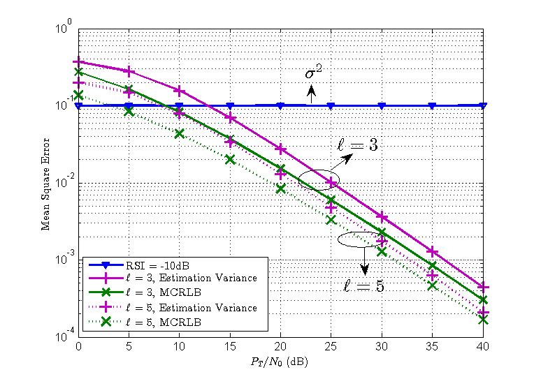
Figure 4 presents the estimation accuracy of the RSI on the relay with respect to a different SNR using different symbol length ![]() .
The MSE is defined as
.
The MSE is defined as ![]() , which is the remaining RSI after estimation and cancellation. As the figure shows, the estimation can significantly reduce the RSI in the high SNR region. Moreover, the variance of the estimation error gradually approaches the MCRLB in the high SNR region Moreover, the variance of the estimation error gradually approaches the MCRLB in the high SNR region
for a given
, which is the remaining RSI after estimation and cancellation. As the figure shows, the estimation can significantly reduce the RSI in the high SNR region. Moreover, the variance of the estimation error gradually approaches the MCRLB in the high SNR region Moreover, the variance of the estimation error gradually approaches the MCRLB in the high SNR region
for a given ![]() ,
given that the variance of estimation error with perfect symbol knowledge can
be regarded as the lower bound of the estimation accuracy, and the estimation
accuracy improves in high SNR. In addition, MSE using
,
given that the variance of estimation error with perfect symbol knowledge can
be regarded as the lower bound of the estimation accuracy, and the estimation
accuracy improves in high SNR. In addition, MSE using ![]() is much smaller than that using
is much smaller than that using ![]() . This observation verifies that an increase in symbol length
. This observation verifies that an increase in symbol length ![]() improves the estimation accuracy.
improves the estimation accuracy.
 at
the relay with respect to SNR using different
at
the relay with respect to SNR using different  .
. 6. Conclusion
In this work, we considered a system with one full-duplex relay that assists the transmission between a single-antenna source and a single-antenna destination. We proposed an STC that estimates the RSI at the relay to achieve diversity gain at the destination. The simulations verified the BER performance with diversity gain of our proposed design.
7. Acknowledgement
The work of Ran Cai and P. C. Ching was partially supported by the HKSAR Research Grant Council under GRF Grant Project #CUHK14201714.
References
[1] V. R. Cadambe, S. A. Jafar, “Degrees of freedom of wireless networks with relays, feedback, cooperation, and full duplex operation,” IEEE Transactions on Information Theory, vol. 55, pp. 2334-2344, 2009. View Article
[2] H. Ju, E. Oh, and D.-S. S. Hong, “Improving efficiency of resource usage in two-hop full duplex relay systems based on resource sharing and interference cancellation,” IEEE Transactions on Wireless Communications , vol. 8, pp. 3933-3938, 2009. View Article
[3] B. Day, A. Margetts, D. Bliss, and P. Schniter, “Full-duplex MIMO relaying: Achievable rate under limited dynamic range,” IEEE Journal on Selected Areas in Communications, vol. 30, pp. 1541-1553, 2012. View Article
[4] Y. Hua, P. Liang, Y. Ma, A. Cirik and Q. Gao, “A method for broadband full-duplex MIMO radio,” IEEE Signal Processing Letters, vol. 19, pp. 793-796, 2012. View Article
[5] I. Krikidis, H. A. Suraweera, S. Yang, and K. Berberidis, “Full-duplex relaying over block fading channel a diversity perspective,” IEEE Transactions on Wireless Communications, vol. 11, pp. 4524-4535, 2012. View Article
[6] I. Krikidis, H. A. Suraweera, P. J. Smith, and C. Yuen, “Full-duplex relay selection for amplifying-and-forward cooperative networks,” IEEE Transactions on Wireless Communications, vol. 11, pp. 4381-4393, 2012. View Article
[7] D. Korpi, T. Riihonen, V. Syrjälä, L. Anttila, M. Valkama, and R. Wichman, “Full-duplex transceiver system calculations: analysis of ADC and linearity challenges,” IEEE Transactions on Wireless Communications, vol. 13, pp. 3821-3836, 2014. View Article
[8] J. I. Choi, M. Jain, K. Srinivasan, P. Levis and S. Katti, “Achieving single channel, full duplex wireless communication,” in Proceedings of the Sixteenth Annual International Conference on Mobile Computing and Networking ACM (Mobicom 2010), Chicago, pp. 1-12, 2010.
[9] M. Jain, J. I. Choi, T. M. Kim, D. Bharadia, S. Seth, K. Srinivasan, P. Levis, S. Katti, and P. Sinha, “Practical, real-time, full duplex wireless,” in Proceedings of the 17th Annual International Conference on Mobile Computing and Networking (Mobicom 2011), Las Vegas, pp. 301-312, 2011.
[10] T. Riihonen, S.Werner, and R.Wichman, “Mitigation of loopback self-interference in full-duplex MIMO relays,” IEEE Transactions on Signal Processing, vol. 59, pp. 5983-5993, 2011. View Article
[11] A. Sahai, G. Patel, and A. Sabwarwal, “Pushing the limits of full duplex: design and real-time implementation,” Rice University, Technical Report TREE1104, 2011. View Article
[12] B. Chun and H. Park, “A spatial-domain joint-nulling method of self-interference in full-duplex relays,” IEEE Communications Letters, vol. 16, pp. 436-438, 2012. View Article
[13] M. Duarte, C. Dick, and A. Sabharwal, “Experiment-driven characterization of full-duplex wireless systems,” IEEE Transactions on Wireless Communications, vol. 11, pp. 4296-4308, 2012. View Article
[14] L. Jiménez-Rodrı́guez, N. H. Tran, and T. Le-Ngoc, “Performance evaluation of full-duplex AF relaying with direct link under residual self-interference,” in Proc. IEEE International Conference on Communications, Sydney, pp. 5723-5727, 2014. View Article
[15] T. Riihonen, S. Werner, and R. Wichman, “Optimized gain control for single-frequence relaying with loop interferene,” IEEE Transactions on Wireless Communications, vol. 8, pp. 2801-2806, 2009. View Article
[16] L. Jiménez-Rodrı́guez, N. H. Tran, and T. Le-Ngoc, “Optimal power allocation and capacity of full-duplex AF relaying under residual self-interference,” IEEE Wireless Commun. Lett., vol. 3, pp. 236–233, April 2014. View Article
[17] Y. Liu, X.-G. Xia, and H. Zhang, “Distributed linear convolutional space-time coding for two-relay full-duplex asynchronous cooperative networks,” IEEE Trans. Wireless Commun., vol. 12, pp. 6406–6417, Dec. 2013. View Article
[18] Y. Liu, X.-G. Xia, and H. Zhang, “Distributed space-time coding for full-duplex asynchronous cooperative communications,” IEEE Trans. Wireless Commun., vol. 11, pp. 2680–2688, July 2012. View Article
[19] J.-S. Han, J.-S. Baek, S. Jeon, and J. S. Seo, “Cooperative networks with amplify-and-forward multiple-full-duplex relays,” IEEE Trans. Wireless Commun., vol. 13, pp. 2137–2149, April 2014. View Article
[20] S. M. Kay, Fundamentals of statistical signal processing – estimation theory, Prentice Hall, 1993. View Book
[21] A. N. D´Andrea, U. Mengali, and R. Reggiannini, “The modified Cremer-Rao bound and its application 8 to synchronization problems,” IEEE Trans. Commun., vol. 42, pp.1391–1399, Feb. 1994. View Article
[22] N. Seshadri and J. H. Winters, “Two signaling schemes for improving the error performance of frequency-division-duplex (FDD) transmission systems using transmitter antenna diversity,” in Proc. IEEE Conf. Veh. Technol., Secaucus, May 18-20, 1993, pp. 508–511.